When designing high-speed digital systems, the purity and distribution quality of clock signals often dictate the ultimate limit of system performance. You might have encountered a scenario where a carefully selected ADC or FPGA underperformed due to poor clock distribution. The LMK1C1102ADQFR, an ultra-low jitter LVCMOS clock buffer, is designed specifically to resolve such issues. With an additive jitter of less than 50 femtoseconds and an output skew below 50 picoseconds, these specifications make it a highly reliable choice for design engineers tackling clock distribution challenges. However, when faced with the dense parameter tables in a datasheet, knowing how to precisely locate the key metrics affecting your design—and avoiding common misinterpretations—is a critical skill every engineer must master.
This article aims to provide an in-depth analysis of the LMK1C1102ADQFR datasheet, breaking down key elements from electrical characteristics and timing parameters to typical application circuits. Through practical examples, we will clarify how these parameters impact real-world system designs, helping you quickly master the design essentials of this high-performance clock buffer while avoiding common pitfalls.
LMK1C1102ADQFR Overview and Core Features
Before diving into the detailed parameters, let's understand the positioning of this device. The LMK1C1102ADQFR belongs to the LMK1C110x family of LVCMOS clock buffers, which offers 1:2, 1:3, and 1:4 fan-out configurations, with our focus here being the 1:2 version. It supports three operating voltages: 1.8V, 2.5V, and 3.3V, allowing you to flexibly adapt to systems with different voltage domains without requiring additional level shifters, thereby simplifying power supply design.
Device Positioning and Technical Advantages
From a performance standpoint, the technical advantages of this device are highly focused. First, the ultra-low additive jitter (50 fs max) ensures signal purity during buffering, which is crucial for high-speed serial links like PCIe, USB, and Ethernet, directly affecting the system bit error rate (BER). Second, the extremely low output skew (under 50 ps) guarantees synchronization between the two outputs, making it ideal for high-precision synchronous sampling systems. Furthermore, its wide operating temperature range (-40°C to +85°C) fully meets the environmental demands of industrial-grade applications.
Pin Functions and Packaging Information
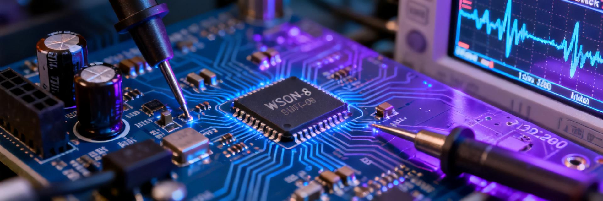
The LMK1C1102ADQFR is housed in a compact WSON-8 package (3mm × 3mm), making it ideal for space-constrained PCB layouts. Its pinout is straightforward: a single clock input (CLKIN), two clock outputs (CLKOUT0 and CLKOUT1), a power pin (VDD), and a ground pin (GND). Notably, it also includes an output enable (OE) pin, facilitating dynamic control of the clock outputs, which is highly beneficial in low-power management scenarios. Packaging parameters such as pin-to-pin capacitance and thermal resistance listed in the datasheet are vital references for your high-speed signal integrity analysis and thermal design evaluation.
In-Depth Interpretation of Core Electrical Characteristics
With a clear understanding of the device's basic positioning, your primary focus should turn to the electrical characteristics table in the datasheet`