In portable medical devices and IoT sensor nodes, the quiescent current of the power management IC often determines the standby lifetime of the entire system. As a low-dropout linear regulator, how much actual benefit does the "low power" feature specified in the TLV74311PDQNR datasheet really bring?
Based on the key parameter curves in the datasheet, this article deconstructs the trade-offs between low-power design and system performance point-by-point, helping you make more informed decisions during component selection.
TLV74311PDQNR Core Parameters at a Glance and Datasheet Structure Analysis
When you get a datasheet, the first step is to locate the electrical characteristics table. The TLV74311PDQNR datasheet puts the input/output voltage range, dropout voltage, and quiescent current in the most prominent positions, as these metrics directly determine whether it fits your low-power scenarios.
Extracting Key Metrics from the Electrical Characteristics Table (Input/Output, Dropout Voltage, Quiescent Current)
The input voltage range is typically 1.7V to 5.5V, and the output is fixed at the 1.1V version. The dropout voltage is typically 130mV at a 200mA load, and the typical quiescent current (IQ) is as low as 25μA. These numbers mean that when the load current drops to the microampere level, the chip's self-consumption is much smaller than the load, and the battery life is almost entirely determined by the load.
| Key Parameter | Typical Value | Test Conditions / Description |
|---|---|---|
| Output Voltage (VOUT) | 1.1 V | Fixed voltage output configuration |
| Input Voltage (VIN) | 1.7V ~ 5.5V | Wide operating input range |
| Rated Output Current (IOUT) | 150mA / 200mA | Maximum drive capability |
| Dropout Voltage (VDO) | 130 mV | Under IOUT = 200mA condition |
| Quiescent Current (IQ) | 25 μA | Under no-load operating condition |
| Shutdown Current (ISD) | 0.1 μA | EN = 0V, disabled state |
How to Interpret Low-Power Related Curves in the Datasheet
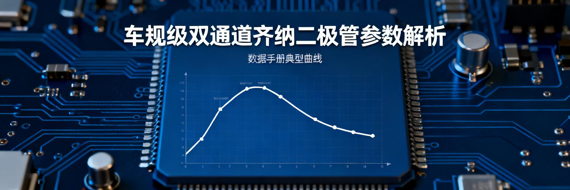
Focus on three curves: IQ vs. temperature, IQ vs. load current, and dropout voltage vs. load current. Within the range of -40°C to 85°C, the fluctuation of IQ is typically less than 10%. If your device operates over a wide temperature range, this curve is the key basis for judging power consumption stability.
The Core of Low-Power Design: The Practical Significance of Quiescent Current and Shutdown Current
The essence of low-power design is not chasing the limit of a single parameter, but making the current consumption of the chip predictable and acceptable in both "standby" and "active" states.
Trends of Quiescent Current (IQ) under Different Loads and Temperatures
The datasheet shows that when the load current rises from 0mA to 1mA, IQ remains basically unchanged; above 1mA, IQ begins to rise with the load. Temperature-wise, IQ is lowest at 25°C and increases slightly at both high and low temperatures. Therefore, if your sensor node is in sleep mode 90% of the time, the low-temperature drift of IQ is a necessary margin to leave when calculating battery life.
Estimating the Practical Impact of Shutdown Current on Battery Life
The typical shutdown current is 0.1 µA. Assuming a 200mAh coin cell battery, if the device remains in shutdown mode for a long time, the theoretical standby time exceeds 200 years—though practically limited by battery self-discharge. However, compared to the standby mode with an IQ of 25 µA, shutdown mode reduces standby current by 250 times. For devices requiring a "shipping mode" or long-term warehousing, this difference directly determines shelf life.
Key Parameter Trade-offs: The Triangular Game of Dropout Voltage, Transient Response, and Power Consumption
It is difficult to optimize low power, low dropout, and fast transient response simultaneously. The trade-off strategy of the TLV74311PDQNR is to prioritize low IQ, keep dropout at a moderate level, and compensate for transient response via external capacitance.
Process Trade-offs between Low Dropout and Low Quiescent Current
The lower the dropout, the larger the size of the internal pass transistor typically needs to be, which also increases leakage current and drives up IQ. Choosing a dropout of around 130mV for the TLV74311PDQNR is the result of balancing IQ and dropout under a 100mA-level load. If your system's input-to-output differential is always greater than 300mV, this dropout specification is completely sufficient.
Indirect Effects of Load Transient Response and Output Capacitor Selection on Power Consumption
The datasheet recommends a 1 µF ceramic output capacitor. Increasing the capacitance can improve transient response but will extend the duration of the inrush current during power-up, indirectly increasing average power consumption. For scenarios with burst RF sensor transmissions, it is recommended to select components according to the recommended datasheet values rather than blindly increasing them.
Thermal Performance and Package Power Dissipation Limits in the Datasheet
Low-power design cannot just look at current; it must also consider whether the package can dissipate heat. The TLV74311PDQNR uses an X2SON package, which has higher thermal resistance, meaning its power dissipation limit is significantly constrained by ambient temperature.
Package Thermal Resistance and Maximum Power Dissipation Calculation
The thermal resistance θJA of the X2SON package is approximately 200°C/W. If the ambient temperature is 60°C and the maximum allowed junction temperature is 125°C, the allowable temperature rise is 65°C, which corresponds to a maximum power dissipation of 65/200 = 0.325W. Under a 1.1V output and 200mA load, if the dropout is 0.5V, the power dissipation is 0.1W, leaving a safe margin.
Derating Recommendations under High Ambient Temperatures
When the ambient temperature exceeds 85°C, it is recommended to derate the load current to below 60% of its rated value. The derating curve in the datasheet shows that at 105°C, the maximum load current is approximately 120mA. If your device is located near a heat source, be sure to leave a margin according to this curve.
Selection and Design Checklist for Low-Power Scenarios
Translating datasheet parameters into design decisions requires a set of actionable verification steps. The following checklist applies to both standby-power-prioritized and dynamic-load scenarios.
Key Configuration Points for Standby-Power-Prioritized Scenarios
- Confirm the maximum value of IQ within the target temperature range, rather than just the typical value.
- The enable pin (EN) must be controlled by the MCU, shut down completely during sleep.
- Use ceramic capacitors with low leakage current for output capacitors, avoiding reverse leakage of tantalum capacitors.
Parameter Verification Steps under Dynamic Load Scenarios
- Find the load transient response curve in the datasheet to confirm whether overshoot/undershoot is within the range allowed by the MCU.
- Calculate the junction temperature at maximum load to ensure it does not exceed 125°C.
- Measure the power-up inrush current to confirm it does not trigger the pre-stage battery protection.
Key Takeaways
- The typical quiescent current of the TLV74311PDQNR is 25 µA and the shutdown current is only 0.1 µA, making it suitable for standby-power-sensitive devices.
- The IQ-temperature curve in the datasheet shows that the IQ fluctuation is less than 10% within -40°C to 85°C; margin must be reserved for low-temperature drift.
- There is a process trade-off between dropout and IQ; a 130 mV dropout at 100 mA load represents a balance point between low power and performance.
- The thermal resistance of the X2SON package is about 200°C/W, and the load current must be reduced according to the derating curve at high ambient temperatures.
- When selecting, prioritize confirming the maximum value of IQ rather than the typical value, and use the EN pin to achieve complete shutdown.
FAQ
Does the quiescent current of the TLV74311PDQNR increase significantly at low temperatures?
According to the datasheet curves, IQ at -40°C increases by about 15% compared to 25°C, remaining in the microampere range. For most coin-cell-powered sensor nodes, this increase has less than a 5% impact on the 10-year lifetime estimation.
How to determine if the TLV74311PDQNR is suitable for RF burst loads based on the datasheet?
Check the load transient response curves. If the overshoot/undershoot is less than 50mV under a 1mA to 100mA step, and your RF module tolerates a ±5% voltage fluctuation, it can be used. Otherwise, you need to increase the output capacitance or choose an LDO with faster transient response.
Can the TLV74311PDQNR completely cut off load power in shutdown mode?
In shutdown mode, the internal pass transistor is turned off, and the output discharges through internal circuitry. However, if there is an external pull-up or back-feed path on the output, an external MOSFET is still required for complete isolation. The 0.1 µA shutdown current in the datasheet only refers to the chip's own consumption.
Under what conditions is the dropout voltage parameter in the datasheet measured?
Dropout voltage is typically measured when the output current is 200mA and the output voltage drops to 98% of its nominal value. Your actual dropout voltage will decrease as the load current drops, and can be less than 50mV at light loads, which is beneficial for low-power designs.