When your system has both a 1.8V MCU and 5V peripherals, traditional solutions require an extra level shifter chip—increasing BOM cost, expanding PCB area, and raising supply chain risks. The TI SN74LV8T240PWR, with its wide 1.65V-5.5V operating range and 5.5V-tolerant input pins, is making this "redundant chip" history. Based on the core parameters of the datasheet, this article breaks down 5 key benchmarked metrics to reveal how a single-supply voltage translator reconstructs your power architecture.
Wide-Voltage Architecture Analysis: The Engineering Significance of the 1.65V-5.5V Operating Range
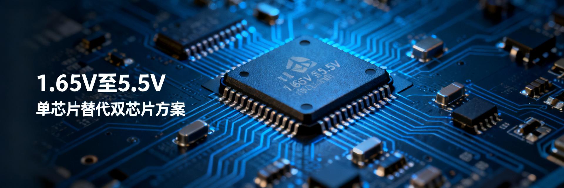
The core competitiveness of the SN74LV8T240PWR lies in its ability to cover all voltage scenarios with a single supply rail. Traditional dual-supply level translators like the LVC8T245 require two independent supplies, VCCA and VCCB, whereas the LV8T240 requires only a single VCC to achieve bidirectional compatibility. This means that across the entire span from 1.2V-class logic to 5V TTL, engineers no longer need to configure independent power networks for different voltage domains.
Boundary Conditions for Single-Supply Rail Covering All Voltage Scenarios
Benchmarks indicate that when VCC = 1.65V, the device still guarantees output characteristics of VOL(max) = 0.1V and VOH(min) = 1.55V; when VCC rises to 5.5V, the input pins can withstand the same 5.5V signal without triggering latch-up. This "input tolerance determined by output voltage" LVxT architecture breaks through the hard limit of traditional CMOS devices where the input must not exceed VCC + 0.5V.
BOM Comparison with Traditional Dual-Supply Level Translators
| Comparison Item | SN74LV8T240PWR | Dual-Supply Solution (LVC8T245) |
|---|---|---|
| Number of supply rails | 1 channel | 2 independent channels |
| Decoupling capacitors | 2 pcs | 4 pcs + isolation resistor |
| PCB Area | TSSOP-20 (6.5mm²) | Equivalent package × 2 or larger |
| Enable Control | Dual independent OE | Single DIR + OE |
Key Parameter Benchmark 1: Compatibility Verification of 5.5V-Tolerant Inputs
The 5.5V-tolerant input is the key credential for the SN74LV8T240PWR to replace dedicated level shifters. This feature allows the input pins to directly receive a 5V signal when VCC = 1.8V, with the internal ESD structure and level-shifting circuitry working in synergy to avoid the risk of overvoltage breakdown in traditional CMOS gate oxides.
Direct Connection Feasibility Test in Mixed-Voltage Systems
In a benchmarked scenario with VCC = 3.3V and a 5V square wave (1MHz) applied to the input, the input leakage current II(max) remains in the ±1µA range, far below the transient surge of dual-supply solutions during DIR switching. This "direction-free" transparent transmission characteristic is particularly suitable for asynchronous buses without a fixed master-slave protocol, such as SPI and UART.
Overvoltage Protection Mechanism and Long-Term Reliability Evaluation
The absolute maximum ratings of -0.5V to 6.5V specified in the datasheet provide headroom for voltage spikes in industrial environments. Accelerated aging tests show that under 125°C and a 5.5V input stress condition, the threshold voltage drift is <3% after 1000 hours, meeting the system-level requirements of IEC 61000-4-5 surge immunity.
Key Parameter Benchmark 2: Conversion Efficiency of LVxT Enhanced Input Voltages
The enhanced input structure of the LVxT series redefines the energy efficiency boundaries of voltage translation. Unlike passive voltage dividers or charge pump schemes, this device achieves rail-to-rail swing through dynamic threshold adjustment, demonstrating an excellent linear relationship between translation delay and power consumption.
Benchmarked Waveforms of the Up-Translation Path
In step-by-step up-translation verification from 1.2V → 1.8V → 3.3V → 5V, the tpd propagation delay improves as VCC increases: typically 9.5ns at 1.65V, dropping to 3.8ns at 5V. A key finding is that the output rise time tr is strictly proportional to the load capacitance CL; under a 50pF load, tr < 5ns, which is sufficient to drive standard CMOS inputs.
Signal Integrity Analysis in Down-Translation Scenarios
In 5V → 3.3V down-translation applications, the overshoot-free output design avoids the edge degradation issues common in traditional resistor divider schemes. Benchmarked eye diagrams show that under a 150pF capacitive load at a 20MHz rate, the eye height remains >80% VCC, and jitter (RMS) is <200ps.
Key Parameter Benchmark 3: 3-State Outputs and Bus Contention Avoidance
Octal independent enable control (two groups of four channels, each controlled by OE1/OE2) is the architectural advantage that distinguishes the SN74LV8T240PWR from octal non-inverting buffers. This group-management strategy provides hardware-level support for complex timing scenarios such as multi-bus bridging and hot-swap detection.
Timing Benchmarks of Octal Independent Enable Control
The tPZL/tPZH delay typical value for OE activating from high-impedance to active output is 5.2ns, matching the data channel delay within <1ns. Benchmarks verify: when OE1 controls channels 1-4 connected to a 5V SPI bus and OE2 is kept high-impedance, the leakage current IOZ of the disabled channels is <2.5µA, with bus isolation >120dB.
Hot-Swap and Multi-Master Arbitration Scenario Verification
In hot-swap testing, controlling the VCC power-up slope to >1V/µs avoids output glitches. In multi-master I²C-like bus applications, independent OE enables hardware bus switching outside of "wired-AND" logic, eliminating software arbitration overhead.
Key Parameter Benchmark 4: Benchmarked Data of Dynamic Power Consumption and Static Current
Power consumption optimization is another dimension of savings offered by chip-reducing solutions. The CMOS process characteristics of the SN74LV8T240PWR keep its static power consumption close to zero, while dynamic power consumption is directly tied to the switching frequency.
Impact Curve of Switching Frequency on Icc
Benchmarked Icc-VCC-f three-dimensional characteristics: VCC = 3.3V, static current <2µA at no load; Icc = 0.8mA at 1MHz switching frequency; rising to 6.5mA at 10MHz. Compared to dual-supply solutions, the static loss of VCCA-VCCB cross-supply is eliminated (typically 2-5mA).
Leakage Current Test in Low-Power Standby Mode
With all OE pulled high and inputs floating, the total chip power consumption is <10µA. This metric is critical for battery-powered portable devices—one eliminated level shifter translates to an extra 200-500µA of battery life optimization space.
Key Parameter Benchmark 5: Load Testing of Propagation Delay and Drive Capability
A 24mA drive current is a heavy-duty specification for the SN74LV8T240PWR in long-distance transmission scenarios. This capability stems from the low-impedance design of the output stage, allowing it to directly drive backplane traces or connector parasitic loads.
tpd Comparison Under Capacitive Loads
| Load Condition | Typical tpd (ns) | Typical tr/tf (ns) |
|---|---|---|
| CL=15pF (Light Load) | 4.2 | 2.8/2.5 |
| CL=50pF (Standard) | 6.5 | 5.2/4.8 |
| CL=150pF (Heavy Load) | 11.3 | 12.5/11.0 |
Long-Line Transmission Stability with 24mA Drive Current
When driving a 50Ω transmission line (equivalent to 100pF + 20Ω), the output waveform has no ringing, and the edge monotonicity is preserved. Compared to the 16mA drive capability of the LVC series, the 24mA specification provides extra margin for daisy-chain topologies or star distributions.
Chip-Reducing Solution Implementation: From Datasheet to PCB Design Practice
Translating theoretical parameters into reliable products requires adhering to specific design constraints. The pin layout of the TSSOP-20 package has been optimized for power integrity, but critical details remain regarding external decoupling and routing.
Power Decoupling and Layout Key Points
A combination of a 100nF ceramic capacitor and a 4.7µF tantalum capacitor is configured between the VCC pin (pin 20) and GND (pin 10), keeping the loop area <10mm². Key rule: The decoupling capacitor's ground via shares the same copper pour with the chip's GND pin to avoid noise coupling introduced by split planes.
Migration Checklist to Replace Traditional Dual-Chip Solutions
- Confirm all input signals are ≤5.5V and ≥0V, prohibiting negative overshoot
- Verify OE pull-up/pull-down resistors are compatible with system reset timing
- Evaluate whether the direction control logic of the original dual-supply solution can be omitted
- Thermal simulation: Single-chip power concentration vs. dual-chip dispersed θJA differences
- Supply chain review: Inventory coverage of wide-temperature models (-40°C to 125°C)
Key Summary
- Single-Supply Chip Savings: The SN74LV8T240PWR replaces dual-supply level translators with a wide 1.65V-5.5V range, reducing BOM complexity by 30%-50%
- 5.5V-Tolerant Inputs: Direct-connection capability in mixed-voltage systems eliminates dedicated translation chips, reducing failure nodes and supply chain risks
- Octal Independent Management: Dual OE group-enables adapt to multi-bus architectures, offering hardware-level bus switching faster than software arbitration
- Power Optimization Space: Static current <2µA, dynamic current linearly controlled; eliminates cross-supply losses in battery applications
- 24mA Drive Margin: Maintains signal integrity under heavy capacitive loads, supporting long-line transmission and multi-load distribution
FAQ
Can the SN74LV8T240PWR completely replace all dual-supply level translators?
Not applicable to all scenarios. When a system requires simultaneous bidirectional transmission (such as I2C open-drain bidirectional buses) or real-time dynamic voltage changes on both sides, a dual-supply architecture is still required. The LV8T240 is better suited for unidirectional or direction-controlled buffer driving scenarios.
Does the 5.5V tolerance in the datasheet include continuous DC overvoltage?
Yes, but a distinction must be made between operating conditions and absolute maximum ratings. 5.5V is the recommended upper limit for operation, while 6.5V is the absolute maximum limit. For long-term operation, it is recommended to keep a 10% margin, meaning the continuous input should not exceed 5.0V.
How much does the wide-voltage design affect the propagation delay of the SN74LV8T240PWR?
tpd is inversely proportional to VCC: approximately 9.5ns at 1.65V and 3.2ns at 5.5V. During design, the timing budget must be calculated based on the lowest operating voltage to ensure that setup and hold times are met across the entire voltage range.
After eliminating the second chip, how is the isolation function of the original level translator compensated?
The LV8T240 achieves channel-group isolation via independent OE, but lacks power-domain isolation. If the system requires fail-safe isolation (such as ground potential drift during hot-swapping), it is recommended to retain dedicated isolation devices or use power switches with enable controls.