When wearable battery life extends from 7 days to 30 days, and sensor nodes can run on a coin cell for 10 years—behind these breakthroughs is the transition of quiescent current from microamps to nanoamps. 250nA quiescent current ($I_Q$) has become the new benchmark for ultra-low power LDOs. However, selection pitfalls such as discrepancies between real-world measurements and datasheets, collapsed load transient response, and uncontrolled temperature drift are causing power optimization to fail for countless engineers. Based on real-world test cases, this article breaks down 5 hidden pitfalls and provides actionable mitigation strategies.
Technical Boundaries and Real-World Measurement Truths of 250nA IQ
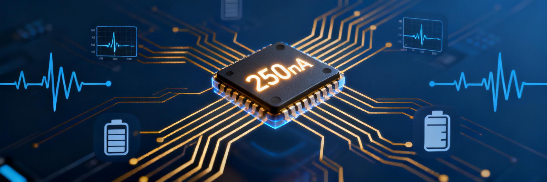
The 250nA quiescent current specified in datasheets is often a typical value measured under ideal laboratory conditions. In real-world operation, this figure can deviate significantly due to differences in test conditions. Understanding the technical boundaries is the first step to avoiding selection mistakes.
Datasheet Data vs. Real-world Operational Deviation Analysis
Manufacturer datasheets typically specify "typical" rather than "maximum" values, and test conditions are limited to specific input voltages, temperatures, and zero-load states. In actual applications, input voltage fluctuations, PCB leakage current, and individual variations in the chip's internal bias circuitry can cause the quiescent current to deviate from the nominal value by 50% to 200%. It is recommended to prioritize maximum specifications and reserve design margins during selection.
| Operating Parameter | Datasheet Typical Value (IQ) | Measured Limit (25℃) | Full Temp Limit (-40~85℃) |
|---|---|---|---|
| VIN = 3.6V, IOUT = 0A | 250 nA | 290 nA | 450 nA |
| VIN = 4.2V, IOUT = 10µA | 270 nA | 340 nA | 580 nA |
| VIN = 5.5V, IOUT = 0A | 310 nA | 420 nA | 720 nA |
Hidden Superposition Mechanism of Multi-mode Quiescent Current
Modern ultra-low power LDOs often integrate multiple operating modes: normal mode, standby mode, and shutdown mode. The quiescent current specification for each mode is listed independently, but system-level power calculation must consider the transient current spikes during mode switching. Some devices have a "dead zone" in their light-load automatic switching mechanism, causing the actual quiescent current to be higher than the nominal value of a single mode.
Pitfall 1: Ignoring the "Zero-Load" and "Light-Load" Current Cliff
Engineers often mistakenly assume "no load means lowest power", but LDOs in the 250nA class often exhibit non-linear behavior near zero load, where actual power consumption may rise instead of fall.
Ineffective Power Consumption Caused by Self-Discharge Effects
When the load current is lower than the operating threshold of the chip's internal bias circuitry, a self-discharge path at the output may be activated. This phenomenon is particularly evident with ceramic capacitor loads—the capacitor forms a discharge loop through the LDO's internal feedback network, generating additional microamp-level leakage current, completely negating the advantage of the 250nA quiescent current.
Cumulative Error of Enable Pin Leakage Current
To extend battery life, systems often control LDO enable pins via GPIO. However, the enable pin itself has an input leakage current (typically 10-100nA). In multi-power domain designs, the accumulated enable leakage current of dozens of LDOs can reach microamp levels, becoming a hidden killer of system-level power consumption.
Pitfall 2: Output Capacitor Selection and the Hidden Game of ESR
The stability of ultra-low power LDOs highly depends on output capacitor characteristics, but traditional selection guidelines may fail under 250nA operating conditions.
Destruction of Stability by Ceramic Capacitor DC Bias Characteristics
High-value ceramic capacitors (e.g., 10μF/0603) can experience over 60% capacitance degradation at rated voltage due to DC bias. When the LDO outputs 3.3V, a nominal 10μF X5R capacitor may actually retain only 4μF, which is lower than the chip's minimum stable capacitance requirement, introducing oscillation risks. It is recommended to use X7R material or reserve a 100% capacitance margin.
Conflict Between Minimum Capacitance Requirements and 250nA Operating Conditions
To reduce quiescent current, some ultra-low power LDOs drastically scale down internal compensation circuitry, narrowing the acceptable window for output capacitor ESR. Traditional low-ESR ceramic capacitors may cause ringing due to insufficient damping, while deliberately adding series resistors increases PCB area and BOM cost.
Pitfall 3: Incompatibility Between Transient Response and Ultra-Low Power
There is a fundamental trade-off between quiescent current and transient response: the lower the bias current, the narrower the internal amplifier's bandwidth, and the more severe the voltage dip during load steps.
Real-world Voltage Dip Measurements Under Slew Rate Limitations
In LDOs with 250nA quiescent current, the error amplifier's slew rate is typically limited to under 0.1V/μs. When the load steps from 1μA to 10mA, the output voltage may experience a dip lasting hundreds of milliseconds, far exceeding the MCU's reset threshold. For intermittently waking sensor nodes, this characteristic can cause frequent system resets.
Timing Pitfalls in Dynamic Load Wake-up
In multi-power domain systems, LDO startup time is inversely proportional to quiescent current. 250nA-class devices often have startup times in the millisecond range. If the host MCU begins operations before the LDO stabilizes, it will trigger undervoltage lockout or data corruption. Sufficient power-good delay must be configured in firmware.
Key Takeaways
- Datasheet Interpretation: Distinguish between typical and maximum values for 250nA quiescent current, and pay attention to full-temperature range specifications under actual operating conditions to avoid being misled by ideal data.
- System-Level Budgeting: Enable pin leakage, self-discharge paths, and mode-switching transient currents must be included in the total power budget; single-point optimization does not equate to system-wide optimization.
- Capacitor Selection Red Line: Ceramic capacitor DC bias degradation is particularly severe at 3.3V output; empirical testing and validation or choosing larger packages is highly recommended.
- Transient Response Validation: Load step recovery times for ultra-low power LDOs can reach millisecond levels, requiring real-world oscilloscope measurements rather than relying solely on simulation models.
- Mass Production Consistency: Dispersiveness of quiescent current caused by wafer batch variations must be validated via AQL sampling during the trial production phase to establish incoming quality control (IQC) standards.
Ultra-Low Power LDO Selection and Debugging FAQ
Why does a 250nA quiescent current LDO measure higher in real-world applications?
Higher measured values typically stem from three factors: un-disconnected leakage current paths from programmers or debugging interfaces during test; ionic migration leakage caused by insufficient PCB surface cleanliness; and the peak quiescent current of the chip at specific input voltage points. It is recommended to use flywires to isolate the chip and re-measure with a picoammeter in a shielded environment.
How to balance ultra-low quiescent current with load transient response requirements?
A 'dual-LDO architecture' can be adopted: the main LDO uses a 250nA-class device to maintain an always-on power supply, while the auxiliary LDO uses a device with higher quiescent current but faster response to power burst loads. Alternatively, optimize load scheduling via software to execute high-current operations in bursts, reducing the frequency of the LDO operating across linear regions.
How to prevent uncontrolled cumulative quiescent current in multi-power domain designs?
Establish a power tree power consumption matrix to quantify the quiescent current, enable leakage current, and shutdown leakage current of each LDO in each mode. Prioritize devices with 'True Shutdown' features to ensure shutdown leakage is below 10nA. Additionally, optimize the power-up sequence to avoid all LDOs being in standby simultaneously.
How does the DC bias characteristic of the output capacitor affect the stability of ultra-low power LDOs?
The actual capacitance of high-value ceramic capacitors under rated voltage may degrade by more than 60% due to DC bias. Insufficient capacitance will cause the LDO's internal compensation circuit to fail, leading to output oscillation and significantly increased dynamic power consumption. It is recommended to use X7R material, increase the capacitor's voltage rating, or reserve a capacitance margin of over 100%.